Hermetic compressor occurs:
1 - as a steel casing consisting of two parts welded electrically to one another and a cylindrical shape.
2 - 2 so that envelope suction pipe, one for the vapors sucked up, the other for filling refrigerant) and a discharge pipe are welded to the envelope.
3 - fixing lugs are welded to the envelope, on which are also located the terminals of the electric motor of the compressor.
role:
its role is to inhale the vapor produced by the evaporation of the refrigerant in
the evaporator has a low pressure, and discharging at a high pressure vapor such
compressed in the condenser.
Principle of operation:
Compressor operation involves two basic steps: the suction and discharge.
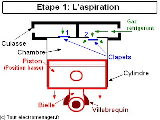
Aspiration:
When the engine is in operation, the rotor rotates and drives a crankshaft which allows the piston to descend in the cylinder by means of the connecting rod. During this phase, the valve 2 opens to the entrance of the refrigerant from the refrigerant circuit of the appliance (gas) in the room.
1 - as a steel casing consisting of two parts welded electrically to one another and a cylindrical shape.
2 - 2 so that envelope suction pipe, one for the vapors sucked up, the other for filling refrigerant) and a discharge pipe are welded to the envelope.
3 - fixing lugs are welded to the envelope, on which are also located the terminals of the electric motor of the compressor.
role:
its role is to inhale the vapor produced by the evaporation of the refrigerant in
the evaporator has a low pressure, and discharging at a high pressure vapor such
compressed in the condenser.
Principle of operation:
Compressor operation involves two basic steps: the suction and discharge.
Aspiration:
When the engine is in operation, the rotor rotates and drives a crankshaft which allows the piston to descend in the cylinder by means of the connecting rod. During this phase, the valve 2 opens to the entrance of the refrigerant from the refrigerant circuit of the appliance (gas) in the room.
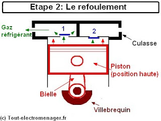
Refoulement:
After entering the refrigerant gas, the piston continued his run and compresses the room. the valve 2 closes tightly. Under pressure the valve 1 can then be opened and exhausting the fluid from directly in the refrigerant circuit of the device. The cycle can then resume
After entering the refrigerant gas, the piston continued his run and compresses the room. the valve 2 closes tightly. Under pressure the valve 1 can then be opened and exhausting the fluid from directly in the refrigerant circuit of the device. The cycle can then resume
During step 1.
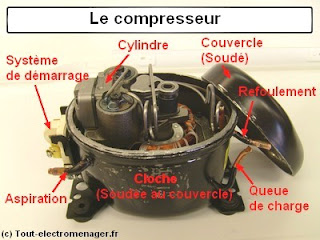
Exploded view of a compressor:
Exploded view of a compressor:

legend:
1 - Cylinder (Power Metal)
2 - suction guide (Oriente gas to the chamber of the cylinder)
3 - Head (Seals between cylinder and valves)
4 - valves (Allow the suction and discharge)
5 - Silent (attenuate the hiss of the gas during the discharge phase)
6 - Cover silent (Provides seal between the muffler and outlet hose)
7 - Pressure hose (Seals of refoulement to the refrigerant circuit)
8 - Counterweight (equilibrium rotational force of the crankshaft)
9 - Piston (Assure gas compression)
10 - Rod (Provides an intermediary between piston and crankshaft)
11 - Crankshaft (Used skewed transmission between rotor and piston)
12 - Rotor (Creates the rotational energy)
13 - Stator (Creates the magnetic field)
14 - spring suspension (balance and stabilize the engine in the bell)
15 - Connection motor (Provides input current in the motor)
16 - Starting system (here CTP)
17 - Oil Pump (lubricates the mechanical mounting)
Compressor start:
We can distinguish two variants starting aid:
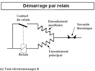
Start relay:
Here is shown in series with the main winding (or "walk") ready to order a relay contact for the supply of the auxiliary winding (or so-called "boot"). When switched on, the electric current required by the main winding is very important. From this fact, the relay (energized) can order contact, feeding the auxiliary winding (start). The engine can then run the current decline in the main winding and therefore the relay (de-energized). Contact will open (off power to the auxiliary winding) and the engine will continue to run on its launched through the main winding. This system is no longer used in modern appliances.
1 - Cylinder (Power Metal)
2 - suction guide (Oriente gas to the chamber of the cylinder)
3 - Head (Seals between cylinder and valves)
4 - valves (Allow the suction and discharge)
5 - Silent (attenuate the hiss of the gas during the discharge phase)
6 - Cover silent (Provides seal between the muffler and outlet hose)
7 - Pressure hose (Seals of refoulement to the refrigerant circuit)
8 - Counterweight (equilibrium rotational force of the crankshaft)
9 - Piston (Assure gas compression)
10 - Rod (Provides an intermediary between piston and crankshaft)
11 - Crankshaft (Used skewed transmission between rotor and piston)
12 - Rotor (Creates the rotational energy)
13 - Stator (Creates the magnetic field)
14 - spring suspension (balance and stabilize the engine in the bell)
15 - Connection motor (Provides input current in the motor)
16 - Starting system (here CTP)
17 - Oil Pump (lubricates the mechanical mounting)
Compressor start:
We can distinguish two variants starting aid:
Start relay:
Here is shown in series with the main winding (or "walk") ready to order a relay contact for the supply of the auxiliary winding (or so-called "boot"). When switched on, the electric current required by the main winding is very important. From this fact, the relay (energized) can order contact, feeding the auxiliary winding (start). The engine can then run the current decline in the main winding and therefore the relay (de-energized). Contact will open (off power to the auxiliary winding) and the engine will continue to run on its launched through the main winding. This system is no longer used in modern appliances.
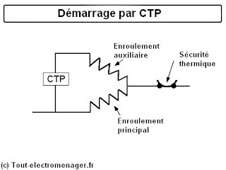
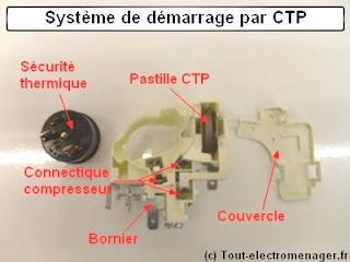
Start by CTP:
This kind of startup is now current on all compressors powering next-generation devices. The CTP is a body whose electrical resistance (ability to curb the current) increases when the temperature increases. A power primary windings (walking) and auxiliary (start) are supplied. The motor can jump. As for the start relay, once started, the auxiliary winding must be cut. This is the CTP will do it. With the current passing through it, it produces heat and, consequently, an increase in its resistance to the complete blockage of the flow of current. The engine is started and fueled the running winding.
This kind of startup is now current on all compressors powering next-generation devices. The CTP is a body whose electrical resistance (ability to curb the current) increases when the temperature increases. A power primary windings (walking) and auxiliary (start) are supplied. The motor can jump. As for the start relay, once started, the auxiliary winding must be cut. This is the CTP will do it. With the current passing through it, it produces heat and, consequently, an increase in its resistance to the complete blockage of the flow of current. The engine is started and fueled the running winding.
Note:
These two starting systems are not interchangeable because they require a clean manufacturing of the compressor motor. On engines start relay, the auxiliary winding is equal to approximately twice the value of the main winding. On starting motors PTC, the values of the two coils are substantially identical.
Thermal safety:
On the schematic above, we can see in series with the motor windings, thermal overload protection. It aims to protect the motor against overheating in case of malfunction. It consists of a bimetallic (alloy of two metals bonded in the form of a disc) which has the particularity to deform under the action of heat. Thus, when the engine overheats, the system cuts power. Similarly, if the engine power at startup, the electric current increases, the bimetallic strip heats up, deform, cut and de facto power.
What symptoms and diagnosis in case of failure?
Not cold in the refrigerator:
Winding-cut: Measure with an ohmmeter
Valve-HS: test compression and suction motor (proper equipment needed)
-Mechanical Problem.
Compressor "click" Thermal safety locks (overheating, boot problem, blocking mechanical problem in the cooling circuit)